As distributors of field instrumentation, Fluidic represent H&B Sensors and commonly supply Pt100 temperature sensors for industrial use. In this short article we would like to briefly explain the basics of a “Pt100” and how is it applied in our industry.
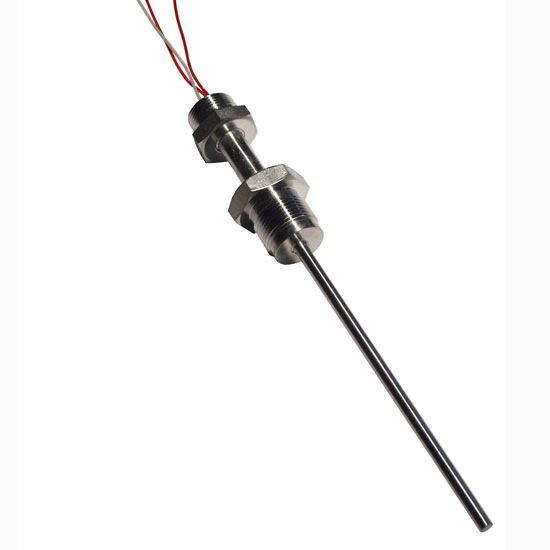
Let’s start with an RTD, or more specifically a Resistance Temperature Detector. An RTD is, quite simply, a very thin piece of metal wire that exhibits resistance change with temperature. This wire is typically wound around a ceramic core, packed with an (electrical insulate but thermally conductive) powder and then fitted inside a metal sheath that can be inserted into the process (commonly via a thermowell).
Various metals can be used for the wire, but critically must be a single metal of high purity. Due to its linear, repeatable characteristics, platinum is often considered best. Purity levels will affect the rate of change of resistance with temperature. Platinum RTDs (i.e. Platinum Resistance Thermometers, or PRTs for short) commonly adhere to a standard, IEC 60751, which includes a common industrial thermal coefficient, α, of 0.00385 Ω/(Ω·°C).
So what is a Pt100? The chemical symbol for platinum is Pt. A “Pt100” is simply a PRT that reads 100Ω at 0°C. When you twin this with the standard industrial α = of 0.00385, then we can provide a full temperature vs resistance chart for a Pt100. Fluidic publish this on our technical links page.
2 wire vs 3 wire vs 4 wire RTDs
Up until now we have discussed the effects of resistance at each end of the thin wire coil. Of course, a Pt100 probe will have an insertion length much longer than the small tip exhibiting this resistance change. Extension wires (with a very slight, but still some) resistance value will run up the probe shaft to the point of measurement (/connection to transmitter).
In a simple, 2 wire RTD then, we actually measure the resistance as…
Actual Measured Resistance therefore = Lead 1 + RTD + Lead 2
This displays an obvious inaccuracy and would cause our “temperature” reading to be slightly higher than actual. To compensate for this, if we can assume that the resistance in “lead 1” and “lead 2″are equal (and they very nearly will be 99% of the time) then let’s use a 3 wire RTD as follows:
If we measure (the relatively low resistance) generated over leads 2 and 3 and subtract this from the measurement taken over lead 1, lead 2 and the RTD then:
Total Measurement = lead 1 + lead 2 + RTD – (lead 2 + lead 3)
Lead 1 = lead 2 = lead 3, let’s just call these “lead”….so…..
Total Measurement = 2* lead + RTD – 2* lead
Total Measurement = RTD
In this way, where critically we assume the resistance in leads 1, 2 and 3 are equal*, hopefully it is clear to see how a 3 wire RTD is used to subtract the resistance caused by “extension leads” in the probe length.
(*In actual fact, the resistance of lead wire 2 is common to both sides of the equation, therefore only really lead wires 1 and 3 must be equal for a 3 wire RTD to completely compensate for lead wire resistance).
Introducing a fourth wire in to the circuit completely eliminates any errors causes by lead wire resistance:
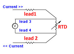
A current of known value is passed through the outer circuit (ie leads 1 and 2) enabling the voltage to be measured directly across the RTD using leads 3 and 4. (The resistance in lead wires 3 and 4 is completely immaterial). Using the equation R = V/I and substituting the known current and measured voltage, the resistance of the RTD can be measured.
The four wire arrangement should be used when accuracy is essential, typically laboratory applications.
Fluidic have a team of instrument engineers that are able to help with product selection. If you have a temperature measurement application, please give your local office a call:
Glasgow on 0141 641 5920 or Warrington on 01925 572401