Reliable airflow measurements in LEV systems
With advances in employee safety, energy efficient plant and an emphasis on continuously improving product quality, industry is beginning to recognise the benefits of an efficient Local Exhaust Ventilation (LEV) system. LEV systems typically run at relatively low air velocities. Obtaining a true measurement of this extraction rate can better help balance the cost of overworking power-hungry extraction systems against dangerously under extracting contaminates and health-adverse fumes.
Traditional pitot tube measurements offer a means of calculating air velocity in a duct by means of pressure measurement. In the duct a static pressure is present along with a pressure caused by the air velocity itself.
The illustration shown below shows the measurement end of a traditional, single point pitot tube. Within the tube itself, two channels are passed up towards the differential pressure instrument.
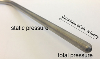
HI side of the instrument collects TOTAL PRESSURE (i.e. velocity pressure + static)
LOW side of the instrument collects only static pressure (perpendicular to the direction of air velocity).
The differential pressure instrument then provides the pressure caused by only the velocity itself. Many differential pressure instruments include a “Square Root Extraction” function to calculate the velocity itself (and linearise the 4-20mA / 0-10V output in terms of a transmitter)…
Due to the very light density of air (1.2041) it is evident that low air velocity will produce low differential pressure measurement. For example, using the equation above, even a relatively ‘strong’ LEV velocity of 3 m/s would only provide a differential pressure of around 5.4 Pa – barely measureable with most instrument technologies.
The solution? There are a couple, depending on the application….
Thermal “hot wire” technology employs a technique of 2 high precision temperature elements (commonly RTDs). One element measures the temperature of the media itself and the other is heated to a set temperature above that of this reference measurement. As the air velocity increased (or reduces) the heated element cools proportionally. This cooling effect requires more (or less) power to maintain the set constant temperature differential. This, in turn, is proportionally conditioned by the transmitter to provide a 4-20mA / 0-10V output. Instruments with “CTA” Thermal Technology (see https://fluidic-ltd.co.uk/news/thermal-mass-flowmeters/ for information specifically on CTA technology) offer a very responsive and reliable measurement even at low air velocity (a typical sensor from Schmidt Technologies can offer its full analogue output over a range as low as 0…1m/s).
Alternatively, Micatrone manufacture a unique pitot tube sensor which amplifies the differential pressure produced by a value of approx 2.2. In the previous calculation of 3m/s this would lead to a differential pressure measurement of around 12Pa – around ¼ scale over the range of the recommended accompanying “Micaflex” 0-50Pa transmitter, getting closer to a workable solution.
So far, we have discussed air velocity measurement, i.e. in m/s. This is because traditional pitot tube and thermal technologies offer a single point measurement in the flow stream. In order to calculate this air velocity as a volumetric air flow, and understand the efficiency of the LEV system itself, it is important that air flow has a known and stable profile. Measurement points should be taken on a long straight section of the duct and “traversed”. That is to say that measurements should be taken at different insertion lengths throughout the duct, to fully understand the flow profile, and then averaged to calculate the true volumetric airflow (remember that even in a stable, laminar flow profile, the velocity may still be around 1.4x faster at the centre of the flow stream due to drag caused by the duct wall). The Micatrone pitot tube mentioned above is of a ‘self-averaging’ design, having several total pressure measurement points across its length. When twinned with the recommended Micaflex transmitter, the duct size may be input to provide a display and 4-20mA / 0-10V output linearised for volumetric airflow measurement.
Download This article was published in The Cleanroom Monitor magazine from S2C2 Issue 66 (Autumn 2014).
For more information on the topic of reliable airflow measurement in LEV systems, including details on the instruments discussed, please contact Fluidic on 0141 641 5920 (Glasgow) or 01925 572401 (Warrington).