InstMC Dinner
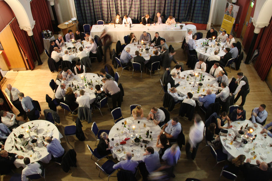
Fluidic were pleased to host a table at the Institute of Measurement and Control, West of Scotland Section Dinner on Friday last week. Looking forward to the upcoming events over the rest of the year.
Fluidic were pleased to host a table at the Institute of Measurement and Control, West of Scotland Section Dinner on Friday last week. Looking forward to the upcoming events over the rest of the year.
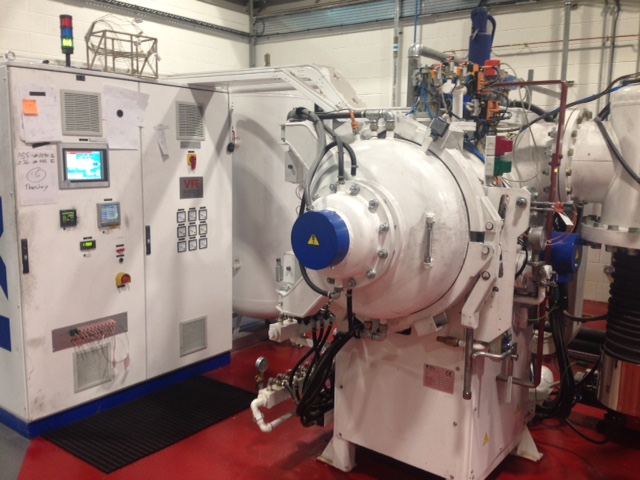
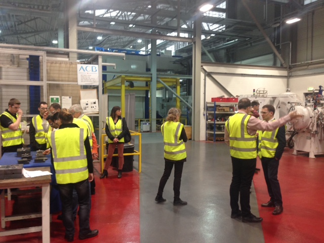
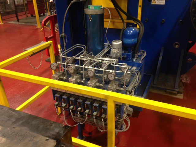
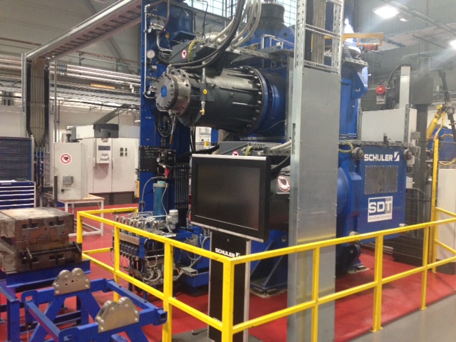
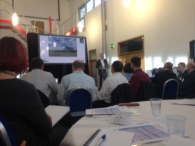
Fluidic had representation at the EMPRESS workshop held in Glasgow’s AFRC (Advanced Forming Research Centre) this week. Some very interesting discussions on the future of high temperature measurement along with a tour of the facility. Some photos below:
Fluidic were very pleased to welcome the Institute of Measurement and Control, West of Scotland section this week for a presentation on “Good Signal Grounding Practices” by our partner Status Instruments. Through distribution from Fluidic, Status offer a range of signal isolators that are ideal to rectify grounding loop issues. Lawrence and Ian offered an insightful, technical discussion on the subject which we hope the institute members found as interesting as us.

As distributors of field instrumentation, Fluidic represent H&B Sensors and commonly supply Pt100 temperature sensors for industrial use. In this short article we would like to briefly explain the basics of a “Pt100” and how is it applied in our industry.
Let’s start with an RTD, or more specifically a Resistance Temperature Detector. An RTD is, quite simply, a very thin piece of metal wire that exhibits resistance change with temperature. This wire is typically wound around a ceramic core, packed with an (electrical insulate but thermally conductive) powder and then fitted inside a metal sheath that can be inserted into the process (commonly via a thermowell).
Various metals can be used for the wire, but critically must be a single metal of high purity. Due to its linear, repeatable characteristics, platinum is often considered best. Purity levels will affect the rate of change of resistance with temperature. Platinum RTDs (i.e. Platinum Resistance Thermometers, or PRTs for short) commonly adhere to a standard, IEC 60751, which includes a common industrial thermal coefficient, α, of 0.00385 Ω/(Ω·°C).
So what is a Pt100? The chemical symbol for platinum is Pt. A “Pt100” is simply a PRT that reads 100Ω at 0°C. When you twin this with the standard industrial α = of 0.00385, then we can provide a full temperature vs resistance chart for a Pt100. Fluidic publish this on our technical links page.
2 wire vs 3 wire vs 4 wire RTDs
Up until now we have discussed the effects of resistance at each end of the thin wire coil. Of course, a Pt100 probe will have an insertion length much longer than the small tip exhibiting this resistance change. Extension wires (with a very slight, but still some) resistance value will run up the probe shaft to the point of measurement (/connection to transmitter).
In a simple, 2 wire RTD then, we actually measure the resistance as…
Actual Measured Resistance therefore = Lead 1 + RTD + Lead 2
This displays an obvious inaccuracy and would cause our “temperature” reading to be slightly higher than actual. To compensate for this, if we can assume that the resistance in “lead 1” and “lead 2″are equal (and they very nearly will be 99% of the time) then let’s use a 3 wire RTD as follows:
If we measure (the relatively low resistance) generated over leads 2 and 3 and subtract this from the measurement taken over lead 1, lead 2 and the RTD then:
Total Measurement = lead 1 + lead 2 + RTD – (lead 2 + lead 3)
Lead 1 = lead 2 = lead 3, let’s just call these “lead”….so…..
Total Measurement = 2* lead + RTD – 2* lead
Total Measurement = RTD
In this way, where critically we assume the resistance in leads 1, 2 and 3 are equal*, hopefully it is clear to see how a 3 wire RTD is used to subtract the resistance caused by “extension leads” in the probe length.
(*In actual fact, the resistance of lead wire 2 is common to both sides of the equation, therefore only really lead wires 1 and 3 must be equal for a 3 wire RTD to completely compensate for lead wire resistance).
Introducing a fourth wire in to the circuit completely eliminates any errors causes by lead wire resistance:
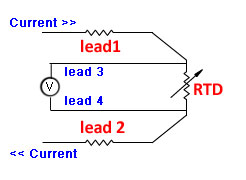
A current of known value is passed through the outer circuit (ie leads 1 and 2) enabling the voltage to be measured directly across the RTD using leads 3 and 4. (The resistance in lead wires 3 and 4 is completely immaterial). Using the equation R = V/I and substituting the known current and measured voltage, the resistance of the RTD can be measured.
The four wire arrangement should be used when accuracy is essential, typically laboratory applications.
Fluidic have a team of instrument engineers that are able to help with product selection. If you have a temperature measurement application, please give your local office a call:
Glasgow on 0141 641 5920 or Warrington on 01925 572401
Fluidic were privileged with the award of Instrumentation Channel Partner of the Year at the recent EMEA Honeywell Channel Partner and User Group conference in the Hague, Netherlands. Approximately 200 distributors across Europe, Middle East and Africa contest for this title annually. Fluidic were singled out for our technical focus and dedication to new, innovative product lines which has grown key accounts across the UK. The attached trophy photo includes some members of our sales team at the event (L-R) Steve Knowles, Catherine Hamilton, Steven Biggs.

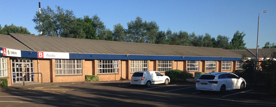
Fluidic are pleased to announce that our Scottish office has moved into new premises. Located just off the M74 (Junction 2A) and with a significantly increased stores capacity, our goal is to improve accessibility for our customer base. We have also increased our in house calibration capacity, offering scope to calibrate pressure, relative humidity, temperature and data-logging / process control instrumentation.
Our new address is Fluidic Ltd, Drumhead Place, Cambuslang, Glasgow, G32 8EY.
Call the office on 0141 641 5920.
Following on from the 2012 EU Energy Efficiency Directive (EED), the UK Government released the Heat Network (Metering and Billing) Regulations 2014. Implementing the requirements in the EED, with respect to the supply of distributed heat, cooling, and hot water.
Stipulated in theses regulations, “It is obligatory for heat suppliers to install sub-meters for heat and cooling where there are multiple tenancies in a single building if it’s technically feasible and cost effective to do so, by 31 Dec 2016.”
“Where a meter to which these regulations apply is installed it must accurately measure, memorise and display the consumption of heating, cooling or hot water by a final customer.”
![]()
The legislation is enforced in the UK by the National Measurement and Regulation Office (NMRO).
The Regulations do not mandate the use of Measuring Instruments Directive (MID) approved heat meters but any meters used for the purpose of these regulations must be accurate and maintained. Installing MID meters would be best practice.
Fluidic Ltd are the Official partner of Micronics, who supply an MID approved In-Line Ultrasonic heat meter, the UF50. The UF50 can be installed horizontally or vertically, on 15, 20 or 25mm diameter pipes. It uses ultrasonic time of flight technology to measure flow rate, and takes temperature readings from both flow and return pipes using pt1000 temperature probes. The heat meter calculates the energy used in kWh.
The UF50 8 digit display can show Energy – Power – Volume – Flow Rate & Temperature. It has an extensive 720 day memory for flow and heat data. The UF50 is IP65 rated and is powered by a 3.6V Lithium battery with a lifespan up to 8 years.
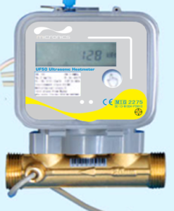
The UF50 communications options are RS485, M-Bus, pulse and optical interface.
The UF50 is an ideal solution for new-build properties, or properties undergoing extensive maintenance, where there is no issue breaking into the line to install.
For applications where this isn’t an option, Fluidic can also supply the Micronics U1000HM.
Although not MID approved, the regulations do not demand this and is perfect for installation on existing pipework where there is no option to interrupt services to install in-line meters. Generally though, we would offer the U1000HM for submetering applications, not for the main billing meter.
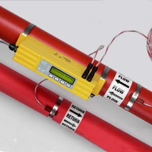 The U1000HM can be installed on a much larger pipe range, 25 – 115mm in diameter, and has a pulse output as standard with Modbus and RS485 communications.
Please find further information regarding the Heat Network (Metering and Billing) Regulations 2014 at https://www.gov.uk/heat-networks
Please contact Fluidic Ltd if you have any further questions about the Regulations, or about the Micronics Heat Meters.
Every day we consume 1kg of food and 2 ltrs of water, but we inhale approximately 20000 litres of air. Since we spend around 90% of our time indoors, the quality of that air must be monitored and conditioned for our comfort, productivity and even our health.
The focus on energy conservation has meant buildings are now being more tightly constructed, placing more emphasis on ventilation and Indoor Air Quality (IAQ). Improving and maintaining Indoor Air Quality not only increases productivity, but can also improve the overall performance and efficiency of HVAC systems.
Well maintained Indoor Air Quality is crucial to avoid what is known as Sick Building Syndrome (SBS). SBS is often caused by poor ventilation and the subsequent air quality. This can cause symptoms in occupants such as dry, itchy eyes and throats. Headaches, lethargy and poor concentration are also common symptoms.
Measuring the IAQ is a vital part of maintaining the ventilation system of a building to prevent SBS and ensure the comfort and health of its occupants. Below are just some of the industry standards acceptable comfort levels for Indoor Air Quality.
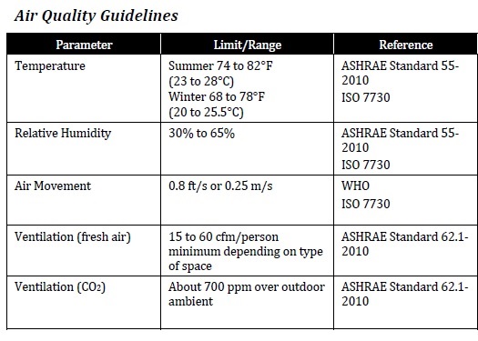
The main parameters measured for IAQ are Temperature, Humidity, CO2 levels and ventilation/drafts. ASHRAE (American Society of Heating, Refrigeration and Air-Conditioning Engineers) and WHO (World Health Organisation) are just two of the governing bodies which help regulate Indoor Air Quality.
Testing of Indoor Air Quality should be routinely carried out to a schedule (generally every 12 months) to comply with regulations, but periodic checks can be carried out in occupied areas using portable equipment. One example of a suitable instrument would be the Dwyer AQH-20 multi-parameter Air Quality meter. Measuring CO2 levels, ambient temperature and relative humidity, the Dwyer AQH-20 is a useful instrument for monitoring IAQ.
The very low velocities to be considered when measuring air movement can be difficult to detect. Fluidic Ltd are the UK distributor for Schmidt Technology. Schmidt offer a full range of flow instrumentation, with some of their sensors capable of measuring directional air flow as low as 0.05m/s. Positioned correctly, Schmidt’s range of instruments, with either switching or transmitter outputs, can help control ventilation to maintain optimum fresh-air flow.
Fluidic Ltd represent a number of manufacturers and our experienced engineers are able to offer advice and support on a wide range of suitable products for indoor air quality monitoring.
The Kurz K-BAR 2000B Multipoint Insertion Flowmeter is an effective, accurate and reliable multipoint flowmeter for many applications. Particularly suited to combustion control and stack emissions monitoring applications.
 The K-BAR 2000B, in conjunction with the ADAM series 155 mass flow computer, forms a flow monitoring system which meets the performance standards for Continuous Monitoring Systems (CEMS). Set out by the Environment Agency under its Monitoring Certification Scheme (MCERTS).
The Environment Agency has established this scheme to deliver quality environmental measurements.
CSA Group (under Sira Certification Service) operates the MCERTS scheme on behalf of the Environment Agency and is accredited by the United Kingdom Accreditation Service (UKAS) to ISO/IEC 17065:2012 ‘Requirements for bodies certifying products, processes and services.’
Fluidic Ltd have represented Kurz Instruments for a number of years and would be happy to discuss any aspects of the Kurz K-Bar 2000B MCERTS approval, or any other enquiries regarding emissions monitoring. Please follow this link to access the Kurz K-Bar 2000B MCERTS approval certificate .
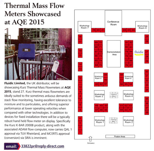
Fluidic are pleased to hold a stand at the upcoming AQE – Air Quality and Emissions – exhibition on April 22nd and 23rd 2015. This year we will be exhibiting our range of thermal mass flowmeters from Kurz, more details above taken from a recent magazine article. Our Howard Feather and David Cairney will be on stand 27 (highlighted in the floorplan above). Please drop by to discuss your AQE application.